IoT-based Distributed, Autonomous and Wireless Heaters
Sophisticated and Magical Heaters Controller was developed. This scheme does not require bi-lateral communication and no data need to be exchanged among the system. However, the heater that requires the most power is given high priority and more power is allocated with no server. This alleviates communication burden drastically. Heaters can be augmented anytime and can be dropped off anytime. This significantly reduces temperature control load and schedule for satellites development. The system is operated via RF and harness design is eliminated. The temperature control system is built quickly and saves tremendous amount of resources. There is only single product type that constitutes the whole system. The product is simply a 45mmx45mm circuit board. This PCB is ready to be provided.
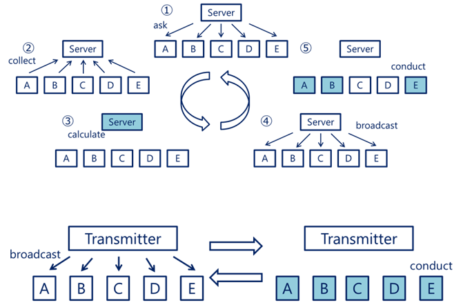
Contemporary control system in principle is based on server-client scheme, in which bi-lateral communication is implicitly and automatically assumed to accomplish the control purpose. This is true for power control. However, the number of property to be controlled is only one, scalar property, 'Power'. Does every information need to be gathered and does the decision need to be made at the central server just in order to control a single property? The answer is clear. Having and piling up bi-lateral communication is huge squander. Building resources such as cost, schedule, man-power explodes and it makes the development difficult.
Satellite development also faces this difficulty. Temperature control in spacecraft development comes latest after all the participating instruments and subsystems finish design process. Usually harness design appears last. Harness mass is not light. Conventional heater control subsystem consists of temperature measurement everywhere and also is constituted of huge number of switches. Which switch be turned on is calculated and decided at the central server, the heater control system. Bilateral communication requests bunch of cables between the server and all the clients, heaters. That is why the mass of harness increases.
Typical server-client system block diagram is illustrated on left. The method developed excludes bi-lateral communication. And whether each heater be on or off is determined at each heater itself. Every heater is provided with only the news on the total power deficit or surplus. It is broadcasted from measurement device that has no brain. Based on the news, each heater performs its independent and autonomous decision. This may sound as if the control results in unharmonious way. However, this distributed system functions well with the special strategy of establishing priority. The heater that requires most power is on first in the system. See the simplified block diagram on left.
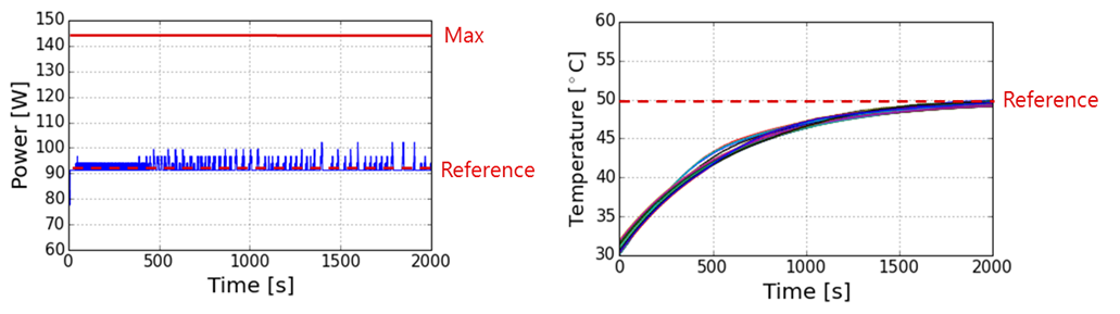
A test example is shown on left. The example presents temperature is well controlled at the target, while the peak of the total power consumption is flattened and suppressed. Flattening heater power fluctuation leads to the available power increase for other subsystems, and the power system aboard is streamlined.
There are given two photos showing the top side and bottom sides of the PCB developed. In this PCB model, arrayed resisters constitute a heater. And the PCB is pasted, and that is all. The power deficit/surplus information is broadcasted by RF devices and there is no harness running inside the spacecraft. Augmenting and removing heaters is arbitrary without affecting system performance. Another photo will tell you how small the PCB developed is. Patchedconics already finished upgraded PCB development, and it is also available and deliverable as of today. One PCB among entire PCBs can play an interface role with the spacecraft data processor. There is no need to report the temperature information for power control. But this PCB system admits gathering temperature information in slow speed not for control purpose but for state observation purpose, in polling manner to make the spacecraft transmit the temperature status to the customer on the ground.
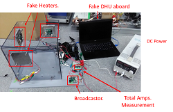
This is just a demonstration purpose but the last image shown on left presents our exhibition demo layout for this distributed IoT heaters system. A PC is connected to simulate the spacecraft bus data processor. A broadcaster module is identical to other heaters distributed in terms of hardware, and connected to the bus data handling system via a serial interface. In this demo layout, a circuit is added to measure the total power consumption. While this is just a demo layout, how simply the system is built is glimpsed by this.
Photos & Drawings

* Any use of the images and the data appear at this web site needs proper admission from relevant copyright holders.